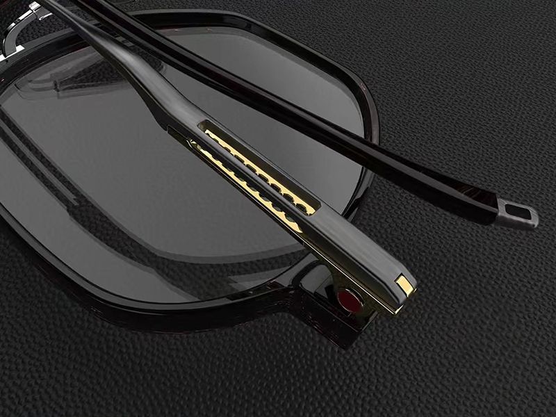
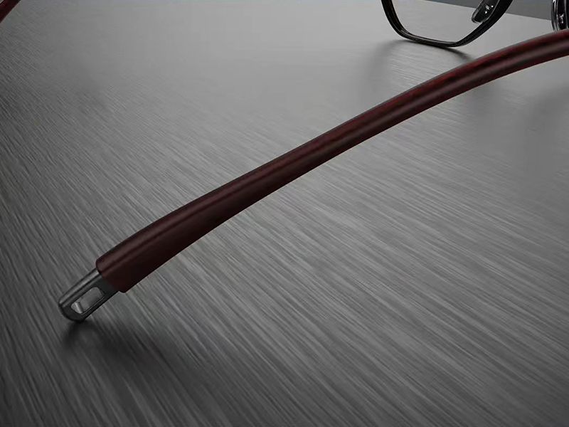
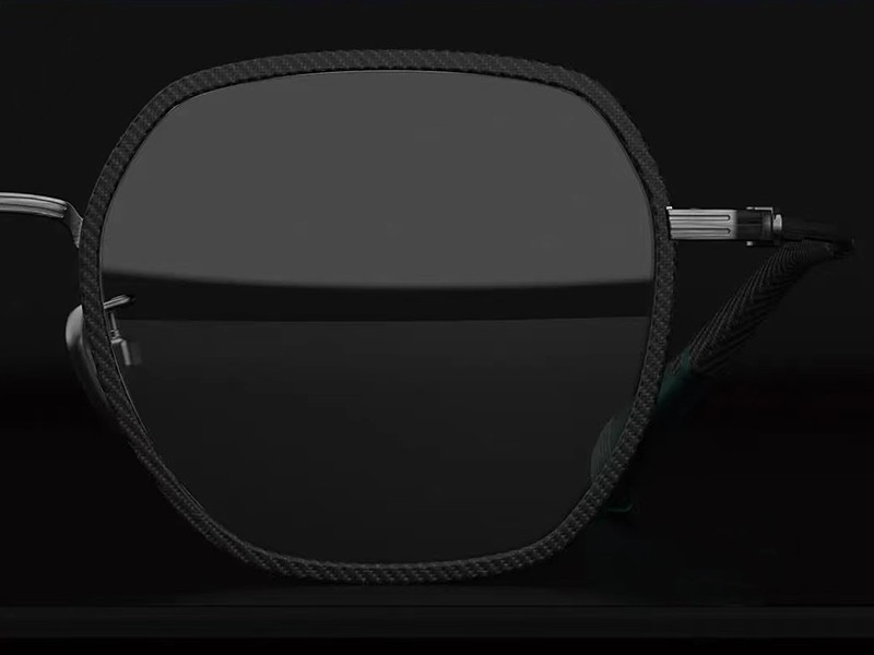
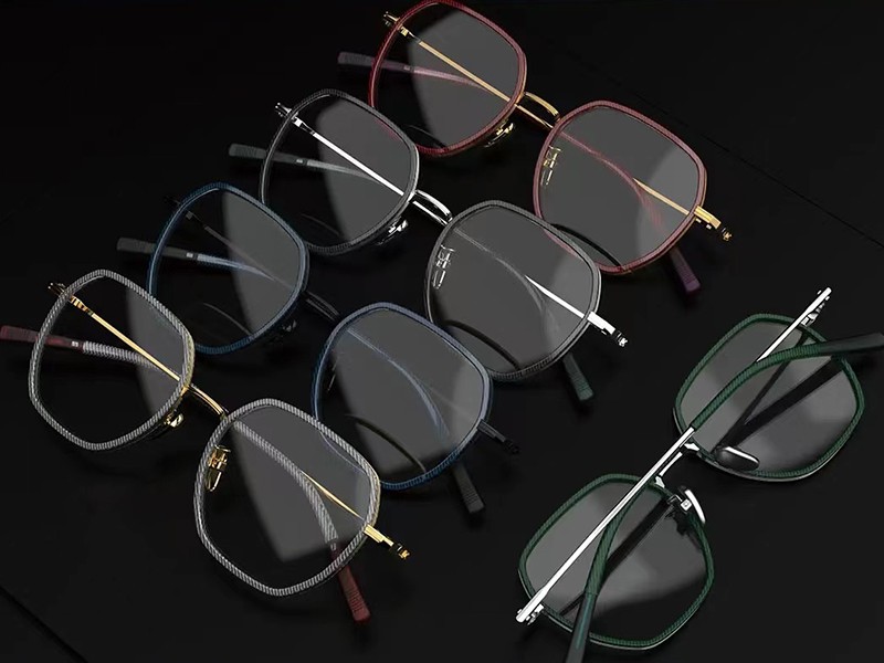
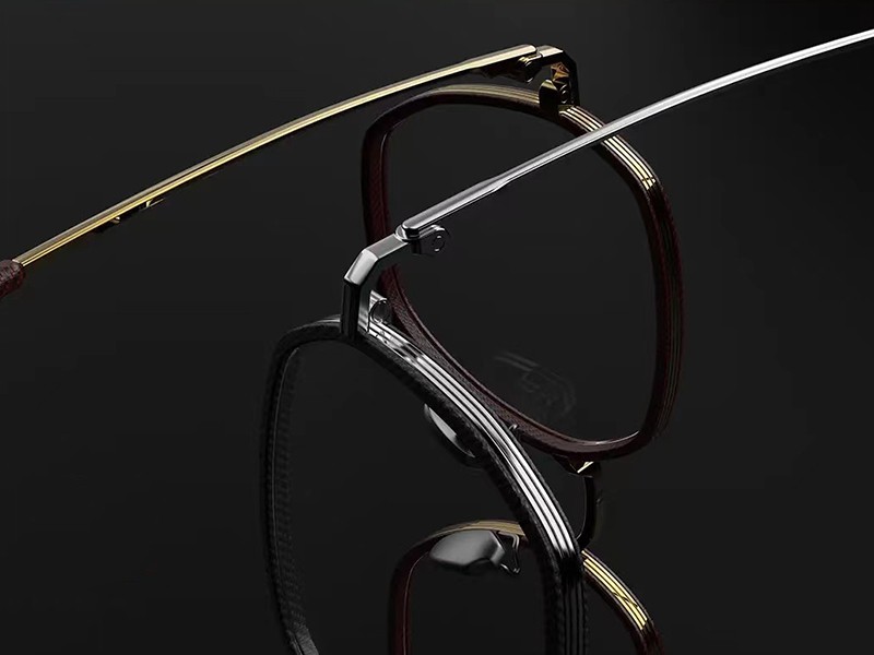
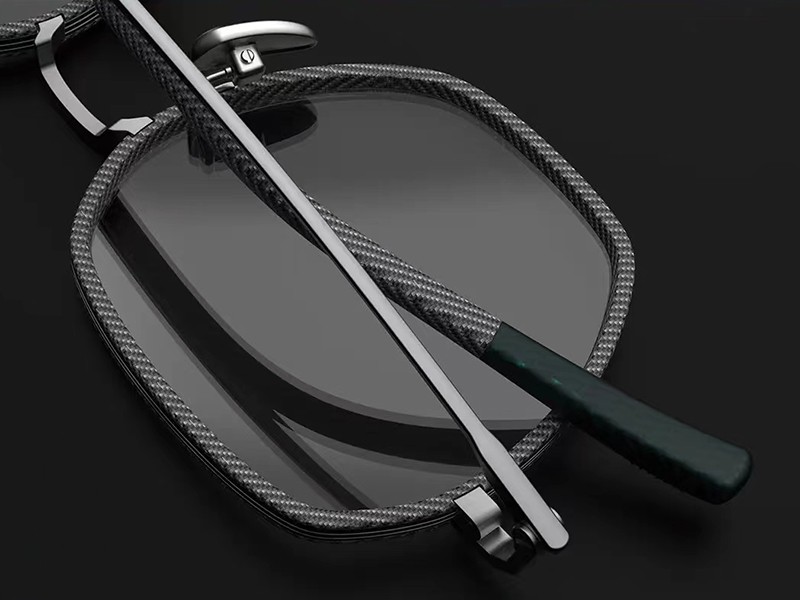
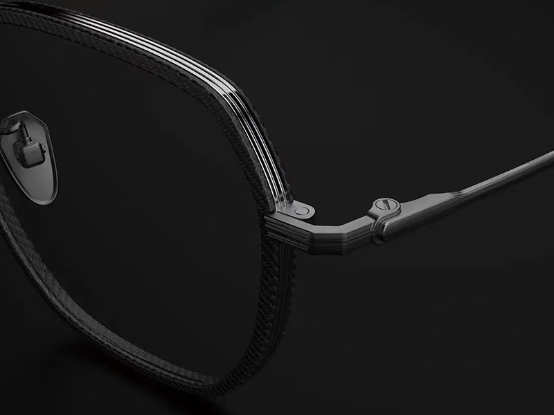
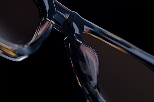
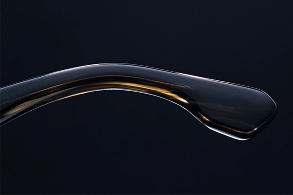
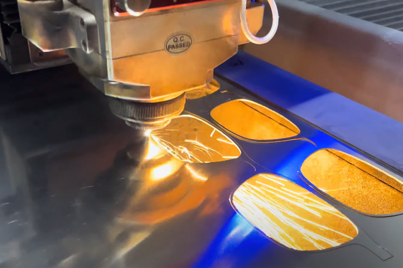
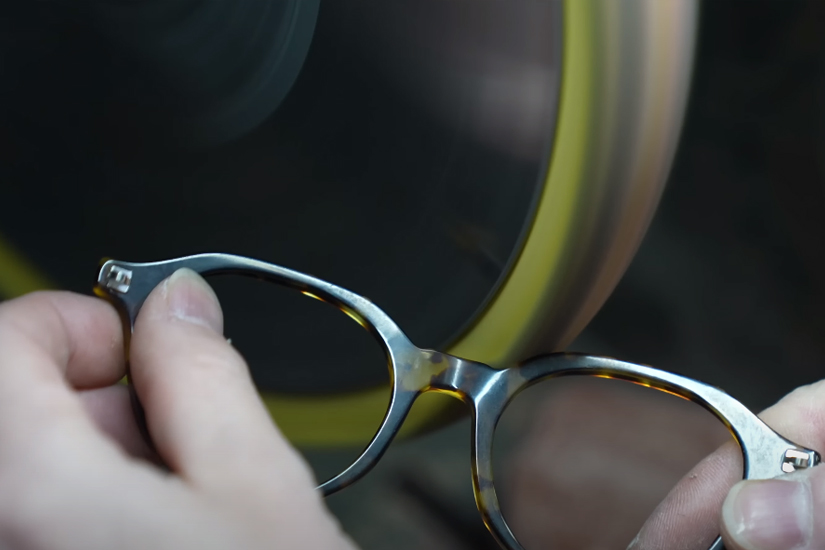
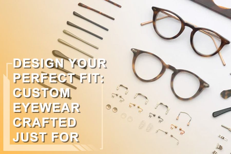
In today’s increasingly competitive global eyewear market, custom design has become the key for eyewear brands to stand out. However, through our extensive work with various clients, we’ve noticed that many brand owners and eyewear businesses with customization needs often face challenges such as inaccurate style positioning, unclear functional requirements, and improper integration of cultural elements. To address these issues, we’ve crafted this blog, “The Ultimate Guide for 2024: How to Design Eyewear,” to provide professional and comprehensive design guidance for eyewear brand customizers. With our years of experience and deep market insights in the eyewear industry, we are confident in offering strong support for your brand’s design journey.
Eyewear Components
When it comes to designing and customizing eyewear, it’s crucial to first understand the basic components of a pair of glasses—just like building a house requires a solid grasp of the foundation and structure. Each part may seem minor, but they all play a vital role.
1. Frame Front
Bridge:This is essentially the “bridge” of the glasses and directly impacts comfort. A well-designed bridge ensures that the glasses stay in place and sit comfortably on your face without slipping.
Rim:The rim acts as the “protective shell” for the lenses. Depending on the design, it can be full-rim, half-rim, or rimless. Each design brings a completely different look and feel to the glasses.
Nose Pads: These small pads are more important than they look—they affect how well the glasses fit and how comfortable they are to wear. The material choice, whether silicone or rubber, can make a significant difference in comfort.
Optical Lenses: This is the most important functional part of the glasses. Without lenses, glasses are like scissors without blades. Optical lenses vary in materials and can be customized with features like anti-reflective or blue light blocking coatings.
Sun Lenses: Sun lenses do more than just make you look cool—they provide crucial protection, especially against UV rays and glare. This is essential for eye health.
Temples: Temples are like the “arms” of the glasses, responsible for keeping the glasses securely on your ears. The length and flexibility of the temples directly impact the stability and comfort of the glasses—this part shouldn’t be overlooked.
Temple Tips: The ends of the temples are often covered with a soft material to enhance comfort because no one wants their ears to be irritated by hard materials.
Hinges: Hinges are the “joints” of the glasses, allowing the temples to fold for easy storage. High-quality hinges are durable and provide the necessary flexibility to ensure that the glasses don’t easily deform or loosen.
5.End Pieces
End Pieces: This part connects the hinges to the frame and, though small, significantly influences the structure and aesthetics of the eyewear.
Designing eyewear is like assembling a puzzle—each component is an essential piece. You can’t focus on just one part while ignoring how it fits into the whole. Each component is interconnected, and they need to work together to create a pair of glasses that is both stylish and functional.
Measuring Sunglasses for Accurate Design
When designing glasses, accurately measuring the frame size is crucial because it directly affects the comfort and visual effect of the eyewear. There are two common methods for measuring sunglasses or other glasses: the baseline notation method and the box notation method. Understanding the differences between these two methods and their applications can help designers ensure precision in the design and production process.
2.1 Baseline Notation Method

The baseline notation method involves measuring the eyeglass frame using the bisector of the parallel tangent lines that pass through the highest and lowest points on the inner edges of the frame or lenses. All vertical measurements start from this baseline. The baseline notation method uses the “-” symbol. For example, if the frame specification is 52-20-140, “52” represents the lens size, “20” represents the bridge size, and “140” represents the temple length (usually measured in millimeters, abbreviated as mm).
2.2 Box Notation Method

The box notation method is widely recognized by the International Organization for Standardization (ISO) and its member countries as a method for measuring eyeglass frames. As the name suggests, the box method involves drawing an outer tangent rectangle (box) that is tangent to the lens bevel. For the corresponding frame, this outer tangent rectangle is also tangent to the eye rim groove of the frame. The box notation method uses the “□” symbol. For example, if the frame size is 52□17-140, this measurement indicates the lens size, bridge size, and temple length. The box method is currently recognized by ISO and all its member countries.
2.3 Comparison Between the Baseline Notation Method and the Box Notation Method

As shown in the diagram, for the same drawing, the lens length measured by the box method is generally greater than that measured by the baseline method, while the bridge size is smaller than that measured by the baseline method. Both methods provide the same lens height. The box method can accurately indicate the lens length and height, but it does not precisely reflect the spacing of the nose pad positions. On the other hand, the baseline method can reflect the nose pad spacing but does not accurately represent the lens length.
In summary, when designing glasses, choosing the appropriate measurement method is crucial for ensuring the accuracy of the design and the final product. The baseline notation method and the box notation method each have their strengths, and designers should select the measurement method that best fits their specific needs.
3.Definition and Identification of Glasses Measurement Items
3.1 Terminology and Definitions for Eyeglass Frame Measurement Items (Using the Box Method for Measurement)
3.1.1 Frame Total Width: The distance between the outermost points of the left and right end pieces when viewed from the front (including the lengths of the left and right lenses, the bridge length, etc.).
3.1.2 Frame Total Length: The distance between the top of the outer front of the frame and the end of the temple arm.
3.1.3 Lens Length: The maximum size of the lens in the horizontal direction. Often denoted by the code “A.”
3.1.4 Lens Height: The maximum size of the lens in the vertical direction. Often denoted by the code “B.”
3.1.5 Lens Spacing: The minimum distance between the left and right lenses. Often denoted by the code “DBL.”
3.1.6 Frame Geometric Center: The distance between the center points of the left and right lenses. Often denoted by the code “FPD.”
3.1.7 Temple Length: The distance from the center of the hinge hole on the temple to the end of the temple tip.
3.1.8 Temple Bend Length: The distance from the center of the hinge hole on the temple arm to the “ear attachment point OBS” on the temple arm.
3.1.9 Temple Drop Length: The distance from the “ear attachment point OBS” on the temple arm to the end of the temple arm. This is commonly referred to as the “temple drop length.”
3.1.10 Temple Drop Angle: The angle between the temple drop length portion and the temple extension line when viewed from the side.
3.1.11 Temple Drop Inward Angle: The angle between the axis of the temple drop length portion and the vertical line when viewed from above, commonly referred to as the “drop inward angle.”
3.1.12 Lens Frame Tilt: When wearing the eyeglass frame and looking straight ahead, the angle between the straight line connecting the upper and lower ends of the front frame and the vertical line when viewed from the side.
3.1.13 Pantoscopic Angle: The angle between the straight line from the center point of the joint between the temple arm and the end piece to the “ear attachment point OBS” on the temple arm and the lens “normal line.”
3.1.14 Nose Pad Spacing: The straight-line distance between the intersection points of the eye rim of the left and right lens frames at the bridge and the vertical centerline of the lenses.
3.1.15 Nose Pad Height: The vertical distance from the highest point of the nose pad leaf when viewed from the side to the outer surface of the lens frame.
3.1.16 Nose Pad Front Angle: The angle between the long axis of the nose pad leaf and the vertical line when viewed from the front.
3.1.17 Nose Pad Top Angle: The angle between the long axis of the nose pad leaf and the back plane of the lens frame when viewed from the side.
3.1.18 Nose Pad Diagonal Angle: The angle between the plane of the nose pad leaf and the normal of the lens frame plane when viewed from above.
3.1.19 Temple Outward Angle: The angle between the connecting line of the left and right hinge axes and the temple arm when the temple arms are opened to their limit when viewed from above.
3.1.20 Frame Curvature: The radius of the arc passing through the endpoints of the left and right lenses when viewed from above, which represents the curvature of the frame.
3.1.21 Lens Plane Angle: The angle between the planes of the left and right lenses when viewed from above.
3.1.22 Temple Bend Spacing: The distance between the inner sides of the left and right temple bends when viewed from above.
3.1.23 Temple End Spacing: The distance between the inner sides of the left and right temple ends when viewed from above.
3.2 Dimensional notation for eyeglass frame measurement items


4. Human Head and Face Features and Glasses Wearing
4.1 Human head and face size
The data in the table below comes from Wikipedia, which is used as a reference when designing our glasses, but at the same time, we will conduct a targeted analysis for our audience.


4.2 Correspondence between eyeglass frame and head-facial measurement items


Face Width: The straight-line distance between the left and right cheekbones.
Full Head Height: The vertical distance between the top of the head and the chin.
Outer Eye Width: The straight-line distance between the outer corners of the left and right eyes.
Inner Eye Width: The straight-line distance between the inner corners of the left and right eyes.
Pupillary Distance: The straight-line distance between the centers of the left and right pupils when looking straight ahead.
Morphological Face Length: The vertical distance between the bridge of the nose and the chin.
Top of Head to Midpoint Between Eyebrows: The vertical distance from the top of the head to the midpoint between the eyebrows.
Eye Top Height: The vertical distance from the top of the head to the inner corner of the eye.
Midpoint Between Eyebrows to Occipital Point: The horizontal straight-line distance from the midpoint between the eyebrows to the occipital point (different from head length).
Midpoint Between Eyebrows to Ear Attachment Point: The horizontal straight-line distance from the midpoint between the eyebrows to the ear attachment point.
Top of Head to Ear Attachment Point: The vertical distance between the top of the head and the ear attachment point.
4.3 Scientific guidance for wearing eyeglasses properly
Frontal Wearing Instructions:

When wearing eyeglasses, the frame width should be as close as possible to the wearer’s face width, and the geometric center distance of the frame should be close to the wearer’s pupillary distance. The center of the pupil should be near the centerline of the B position of the lens, ensuring that the horizontal and vertical deviations of the lens optical center are within the acceptable range.
If the frame width is too large, the eyeglasses may easily slip off when worn; if the frame width is too small, the wearer’s face will bear increased pressure from the frame, affecting comfort and potentially causing frame deformation. Frame width is also related to the structure; relatively speaking, spring hinge frames have a slightly smaller width than ordinary hinge frames because the temples of spring hinge frames have an outward tension.
Additionally, the front angles and spacing of the left and right nose pads should be consistent with the wearer’s nose shape to ensure comfortable eyeglass wear. Nose pads come in adjustable and fixed types. Adjustable nose pads can be adjusted according to the wearer’s nose shape, while fixed nose pads require a good fit with the wearer’s nose shape to ensure comfort.
Side View Wearing Instructions :

From a side view of the human body, the upper edge of the eye socket is more protruding than the lower edge. When wearing eyeglasses, the lens frame needs to be tilted to ensure comfortable and aesthetically pleasing wear. If the lens frame tilt is too large or too small, it can cause discomfort and result in astigmatism. The tilt of the lens frame is directly related to the tilt of the temples, and their relationship changes with the position of the ear attachment.
When wearing the eyeglass frame, ensure that the curve of the temple is at the position of the ear. The temple’s downward angle is typically 35°±5° (excluding sports models). If the angle is too small, the frame may slip off easily; if the angle is too large, it can make putting on and taking off the glasses inconvenient. The radius of the temple’s curved angle is usually R50±5.
Additionally, when viewed from the side, the height of the nose pads should ensure that the wearer’s cornea is 12mm away from the bottom of the lens, also known as the “vertex distance.” Adjustable nose pads can meet the vertex distance requirements by adjusting the top angle of the pad, achieving optimal visual effects. Fixed nose pads, on the other hand, require a good fit with the wearer’s nose shape to ensure comfort.
Top View Wearing Instructions :

When wearing eyeglasses, viewed from the top, the distance between the left and right temples and the vertical inner angle of the temples should fit the wearer’s head shape to ensure stable, comfortable wear and to prevent the glasses from slipping. The temple spacing should be adjusted according to the frame structure. For example, the temple spacing of ordinary hinge frames should be 4-8mm larger than that of spring hinge frames, and the temple spacing of spring hinge frames should be 6-10mm larger than that of “ultra-elastic” frames (depending on the frame’s elasticity).
From a top view, the top angle of the nose pads should fit the wearer’s nose sides to ensure wearing comfort. If they do not match, pressure marks from the nose pads may appear on the nose.
Additionally, the angle between the lenses and the curvature of the lens frame should be determined according to the frame’s functional type. The curvature of ordinary prescription frames should be smaller than that of sunglasses. (See the subsequent design instructions for more details)
5. Designing Eyewear

5.1 Eyeglass frame design principles
Stability : Stability in eyeglasses means keeping them balanced and steady during use. It’s important for users because it affects how the glasses feel and perform while being worn. To improve stability, make sure the frame fits well on the head, the temples and nose pads are comfortable, and the lenses are at the right distance from the eyes. This ensures better comfort and vision for the wearer.
Mechanical Properties : During use, eyeglasses are subject to the force of gravity, which is related to the mechanical effects found in physical properties. However, more importantly, the design of the eyeglasses should have a structural form that suits these mechanical characteristics. This ensures that the glasses remain stable and comfortable on the wearer’s face while resisting the forces acting upon them.
Comfort : Eyeglass wearers can clearly feel the comfort of their glasses. While glasses bring convenience to people’s lives, comfort is also very important. As an assistive tool for those with nearsightedness, glasses should not become a burden. A well-designed frame that fits the wearer’s face shape, along with appropriate temple curves, nose pads, and lens distance, can enhance the overall comfort of the eyeglasses, making them a pleasure to wear.
Aesthetics : The eyes are the window to the soul, and choosing suitable eyeglasses can highlight one’s personal style. Unique design elements in the frame can make the glasses visually appealing and enhance the wearer’s overall appearance. Selecting the right shape, color, and style of the eyeglass frame can complement the wearer’s facial features and help express their individuality.
5.2 Front rim design of eyeglass frames
Principle: There should be no fixed limitations on the shape, and the size should meet the wearer’s requirements. The main points are as follows:
5.2.1 Lens Frame Length : When designing the lens frame length, consider the wearer’s “eye fissure” length. The length of the lens frame must be greater than the length of the “eye fissure.” This ensures that the lenses adequately cover the wearer’s eyes, providing proper visual support and a comfortable fit.

5.2.2 Lens (eye rim) Height : When designing the height of the lens frame, first determine the position of the wearer’s pupil within the frame. Aim to have the center of the pupil aligned with the vertical centerline of the lens frame. Additionally, from an aesthetic perspective, the upper edge of the lens (eye rim) should not exceed the horizontal line at the “midpoint between the eyebrows.” It can be level with or below this horizontal line. Consider these factors comprehensively to ultimately determine the height of the lens (eye rim) frame.

5.2.3 Frame Front Width : When designing the frame front width, consider the facial features of the eyeglass wearer, such as face width, outer eye width, and pupil distance, among others. The relationship between these facial parameters and the eyeglass frame is as follows:

Face Width and Frame Total Width : From an aesthetic perspective, the frame width should match the face width of the eyeglass wearer, blending the frame with the wearer’s facial features. This ensures a comfortable and visually pleasing fit. (The average face width for adults is 143mm for men and 136mm for women.) From a comfort standpoint, it is essential first to ensure that the frame is stable, secure, and not prone to slipping. Moreover, the frame should not be too tight, causing discomfort by squeezing the head.
Outer Eye Width and Outer Width of Both Lens (eye rim) Frames : The outer width of both lens (eye rim) frames must be greater than the outer eye width,This ensures that the frame provides adequate coverage of the wearer’s eyes and offers a comfortable and secure fit.
Pupil Distance, Lens Length, and Bridge Length : When designing, first consider the target group’s pupil distance. The length of a single lens plus the bridge length should be as close as possible to the eyeglass wearer’s pupil distance.This ensures that the glasses are properly aligned with the wearer’s eyes, providing optimal vision correction and comfort.
5.2.4 Frame Front Nose Pad Support : The shape of the nose pad support area of the lens (eye rim) frame should conform to the facial features of the target group, ensuring a stable and comfortable fit. Nose pad supports can be divided into fixed and adjustable types. Adjustable nose pad supports can be adjusted according to the wearer’s facial features, while fixed nose pad supports cannot be adjusted. Therefore, the design of the lens (eye rim) frame should take into account the shape and spacing of the nose pad support area. (During the design process, a standard nasal bone model can be used for fitting tests to ensure that it meets the wearing requirements)

5.2.5 Summary of front frame design:
Frame eye shape has no fixed limitations and can be chosen based on the wearer’s face shape.
The overall length of the front frame should correspond to the wearer’s face width. The length of a single lens (eye rim) frame plus the bridge length should be as close as possible to the wearer’s pupil distance.
The center of the wearer’s pupil should be as close as possible to the vertical centerline of the lens (eye rim) frame height.
Use a nasal bone model for fitting tests at the nose pad support area of the lens (eye rim) frame to ensure that the frame meets the wearer’s requirements.
5.3 Curvature and lens angle design for eyeglass frames
When designing the lens frame curvature and lens angle, consider the target group’s brow contour in a top-down view and the frame’s functionality. The lens frame curvature and lens angle are correlated; the greater the curvature, the larger the angle. Conventional lens frame curvature and lens angles are as follows:

400C-500C angle of 5-8 degrees (commonly used for prescription eyeglasses frames)
600C angle of 9-12 degrees (commonly used for regular sunglasses frames)
800C angle of 13 degrees and above (commonly used for sports eyeglasses frames and other special frames)

These curvature and angle ranges ensure that the eyeglass frames provide the appropriate coverage and functionality for their intended use, whether it is for prescription glasses, sunglasses, or sports and specialty eyewear.
5.4 Nose pad design for eyeglass frames
Ensure the eyeglass frame is comfortable and stable when worn.
When designing the nose pad support, consider the target group’s nasal features to meet their wearing requirements. The main aspects to consider are the distance between the two nose pad supports, the front angle of the nose pad support, the top angle of the nose pad support, the oblique angle of the nose pad support, the position of the nose pad support, and the height of the nose pad support. The details are as follows:
5.4.1 Distance between the two nose pad supports: The distance between the two nose pad supports has already been determined during the design of the front frame of the eyeglasses.
5.4.2 Nose Pad Angles : There are three angles to consider for the nose support – the front angle, the top angle, and the oblique angle.


5.4.3 Nose Pad Support Position : The upper part of the nose consists of hard “nasal bones,” while the rest is made up of soft tissue. When wearing glasses, the nose pad support should be positioned on the wearer’s “nasal bone” to ensure a stable fit and prevent the glasses from slipping. The position of the nose pad support directly determines the position of the lens frame on the wearer’s face. Considering the facial features of the human head, the design position can place the “most prominent point” of the nose pad support inward, aligned with the horizontal midline of the B position of the lens (eye rim)frame (the baseline of the baseline method).

5.4.4 Nose Pad Height : When designing the nose support, consider the vertex distance (usually 12mm). The vertex distance refers to the distance between the back vertex of the lens and the cornea. This consideration helps ensure proper positioning and comfort for the wearer.

5.5 Temple design for eyeglass frames
Ensure the eyeglass frame is comfortable and stable when worn.
5.5.1 Temple Length : This refers to the distance between the hinge hole center and the end of the temple. When designing the temple length, consider the target group’s head length, as well as the frame’s curvature and the type of temple tips. Reference szie for frame total length:
Taking these factors into account will help create eyeglass frames that provide a comfortable and secure fit for the intended age group.

Curved end piece:
Children’s frames temple length: 110mm-125mm
Adult frames temple length: 130mm-145mm
Straight end piece :
Children’s frames temple length: 115mm-130mm
Adult frames temple length: 135mm-150mm
These suggested temple lengths for both curved and straight temple tips can ensure a comfortable and secure fit for children and adult eyeglass frames.
5.5.2 Temple curvature design: Ensure the eyeglass frame is comfortable, secure, and convenient to put on and remove.

Temple drop angle and temple spacing: Design both the pantoscopic angle and temple spacing to ensure a comfortable and secure fit for the eyeglass frame. The pantoscopic angle and temple spacing should be determined according to the frame’s “elasticity.” The pantoscopic angle and temple spacing for ultra-flexible frames differ from those of regular frames.

The angle between the vertical length axis of the temple and its extended line. The design typically ranges between 30-35° (excluding sports frames) and can be adjusted according to the consumer’s facial features during eyeglass frame sales.


5.6 Calculating the pantoscopic angle of the eyeglass frame
Pantoscopic angle of the eyeglass frame refers to the angle between the straight line from the center point of the temple and temple tip joint to the “attachment point above the ear (OBS)” and the “normal line” of the lens. Since the “attachment point above the ear” and the “normal line” of the lens remain fixed when wearing the eyeglass frame, the position of the temple’s joint with the temple tip determines the temple tilt. The higher the end piece position, the greater the pantoscopic angle.

Please note:
The front frame tilt conforms to the slant of the upper and lower edges of the eye socket on the side view of a person’s head.
The pantoscopic angle is directly related to the position of the temple tip on the eyeglass frame; the higher the end piece, the greater the pantoscopic angle. (During sunglasses production, the size marked on the drawings and the actual measured size in production usually represent the pantoscopic angle.)
The pantoscopic angle should be accurately calculated during the designing sunglasses process, as most eyeglass frames have non-adjustable angle. The strength of the temple tip is a crucial part of the overall frame strength. If the frame pantoscopic angle can be adjusted, it could indicate that the overall strength of the frame is insufficient, making it prone to deformation when worn. Besides, adjusting the pantoscopic angle might lead to the temple tip losing color or plier marks appearing.
5.7 Process and tools for eyewear designing
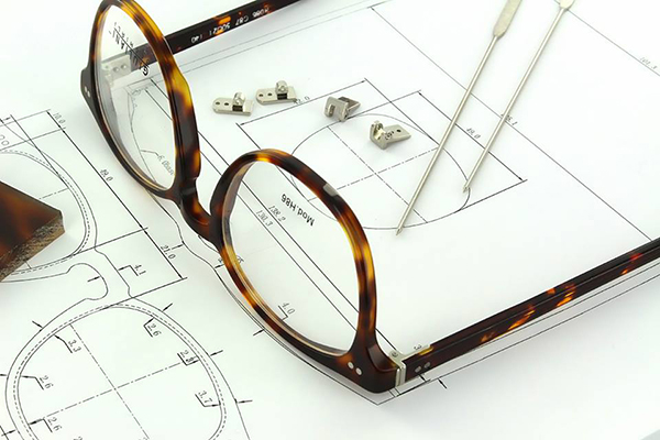
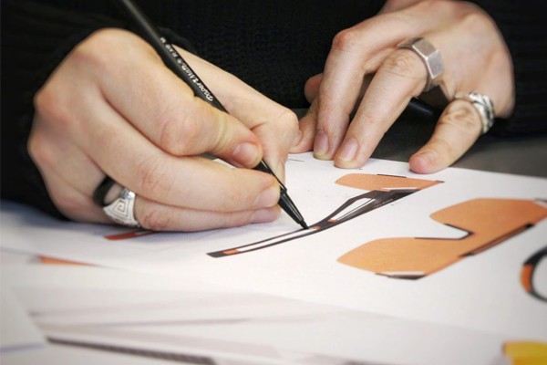
5.7.1 Sunglasses Sketch : The development of a product and designing sunglasses does not come from nothing or without reason; it is always the result of thorough market research and analysis of popular trends within a specific framework. Our designs revolve around the overarching framework of a brand, with the brand style and elements remaining relatively constant. First, we create sketches based on the brand’s style and tone using tools like mechanical pencils and curve boards. An example is shown in the image below:

5.7.2 Import the sketches into sunglass design software CorelDRAW (CDR) or Adobe Illustrator (AI) to develop a more accurate two-dimensional design draft.

Once the linework is sketched, the mechanical process of drawing occurs, as shown in the complete image below:

5.7.3 Transfer to eyewear design software Photoshop (PS) to add color to the product.

5.7.4 Make 3D drawings
5.8 Other considerations in eyeglass design
5.8.1 Material selection: Ensure compliance with the legal requirements of different regions, making sure the materials are non-toxic and harmless. Refer to the REACH regulation.
5.8.2 Frame strength: Eyeglass frames can become deformed after being worn for a period of time, which may be caused by insufficient frame strength. During the design process, it is important to assess frame strength. (For more details, see the eyeglass frame testing instructions in the following chapter.)
6.Analyze the Design Files
6.1. Dimensional Accuracy Check
After completing the CAD design, the first step is to check the accuracy of all key component dimensions. For example, the length, width, and height of the frame must strictly align with the design specifications. Otherwise, it could lead to issues like looseness or discomfort during use. It is also essential to consider the tolerance range common in production, especially for connection points and the curvature of the temples, as any inaccuracies could directly impact the comfort and lifespan of the eyewear.
Example: If the frame width is 0.5mm smaller than the standard requirement, the lenses might not fit properly, or they might become loose after installation, affecting the product’s durability and the wearer’s experience.
6.2. Material Suitability Analysis
Material selection is critical to the success of the design. Different materials have unique physical properties, such as elasticity, strength, and wear resistance. After completing the CAD design, it’s essential to analyze whether these materials are suitable for each component of the eyewear. For instance, plastic materials offer good elasticity and are suitable for making frames, but they may deform under high temperatures. On the other hand, metal materials, although durable, might require consideration of weight and processing difficulty.
Example: If you design a metal frame without considering its weight, the final product might put excessive pressure on the nose bridge, affecting wearing comfort.
6.3. Functionality Testing
The main goal of the design is to ensure the functionality of the eyewear. Incorrect temple length might cause the glasses to slip off easily, while insufficient frame stability could lead to the lenses becoming loose or falling out during use. Functionality testing in the CAD model can simulate how the eyewear will perform in real-life use, allowing you to identify and correct potential issues promptly.
Example: Suppose the temples are designed too long; this could make it difficult for the glasses to stay securely behind the ears, requiring the wearer to adjust their position frequently, thus affecting the user experience.
6.4. Structural Integrity Review
The structure of the eyewear must be robust and durable, with all components tightly connected. Structural integrity review involves evaluating whether each component in the CAD design can seamlessly connect to form a sturdy whole. This is especially critical for the hinge area, which must withstand repeated opening and closing without becoming loose.
Example: If the CAD model reveals that the design of the hinge connection lacks sufficient strength, it could result in the product breaking easily during use, thus compromising its durability.
6.5. Manufacturability Assessment
Even the most perfect design is futile if it cannot be manufactured. After completing the CAD design, it’s crucial to assess the manufacturability of the design. Check whether specific processes are required or if there are components that are difficult and costly to produce. Ensure the design can be smoothly manufactured within the existing production lines and technological conditions, and is suitable for mass production.
Example: If the CAD design includes overly complex surfaces, it may require additional processes or molds during production, increasing production costs, and ultimately affecting the product’s market price and competitiveness.
6.6. Aesthetic and Comfort Review
Eyewear is not only a functional product but also a fashion accessory. Therefore, after completing the CAD design, it’s necessary to review the aesthetics and comfort of the product. The design should align with current trends while ensuring that it does not cause discomfort during prolonged wear. Ensure that the design is visually appealing and comfortable to wear.
Example: If the frame shape doesn’t match current fashion trends, the product might not gain much market acceptance, no matter how functional it is. Additionally, a design that is too tight could press against the head, causing headaches or discomfort after prolonged wear.
7. Modify the Design Files
After completing the initial analysis and checks, it’s often necessary to modify the CAD design files to address any issues identified during the review process. This step involves making precise adjustments to dimensions, materials, or structural components to ensure the design meets all functional, aesthetic, and manufacturability requirements. Modifying the design files also includes updating the CAD model to reflect any changes, ensuring that all details are accurately captured for production.
If the initial review reveals that the frame is too thin to support the lenses securely, you may need to thicken certain sections of the frame in the CAD file. This adjustment can prevent potential issues during manufacturing and ensure the final product is both durable and functional.
8. Confirm the CAD Files
Once all necessary modifications have been made, the final step is to confirm the CAD files. This involves a thorough review to ensure that all adjustments have been correctly implemented and that the design is fully optimized for production. Confirming the CAD files means verifying that the design is complete, accurate, and ready for manufacturing. It also includes checking that the files are properly formatted and compatible with the production equipment and software used by the by the manufacturer.
Before sending the CAD files to the manufacturer, you should conduct a final review to ensure that all dimensions, materials, and components align with the design specifications. This confirmation step helps prevent any last-minute issues that could delay production or result in costly errors.
Begin Prototyping
After finalizing the CAD or 3D design of the eyewear, the next step is to begin prototyping. Whether it’s done by hand or through a factory, every stage of the prototyping process must be meticulously controlled. The following are the key steps involved in the prototyping process:
| Step | Description | Importance |
| 1. Confirm Design Files | Confirm the final CAD or 3D design files with the factory. Provide actual photos or videos as references to ensure the factory accurately understands the design intent. | Prevent production deviations |
| 2. Confirm Materials and Colors | Confirm the material types (e.g., metal, plastic, etc.) and color options according to the design requirements to ensure the final product’s appearance and durability. | Ensure design compliance |
| 3. Prepare Materials and Confirm Prototyping Timeline | Verify the availability of all materials, confirm the prototyping timeline, and ensure materials are prepared on time to avoid delays. | Control production schedule |
| 4. Quotation | The factory will provide a quotation based on the design complexity, material costs, and craftsmanship. Ensure the costs are reasonable and include all necessary services. | Ensure cost control |
| 5. Prototyping | The factory will create the prototype based on the confirmed design and materials. Perform a strict quality check to ensure the prototype meets all design specifications. | Ensure final product quality |
Detailed Step Descriptions:
1. Confirm Design Files
First, you need to confirm the final eyewear design files with the factory. This includes detailed CAD files or 3D models that will guide the factory’s production process. To ensure mutual understanding, you can provide actual photos or videos as reference materials, helping the factory accurately grasp the design intent. This step is crucial to avoid any deviations during production.
2. Confirm Materials and Colors
Before prototyping, it’s essential to confirm the materials and colors. Determine the types of materials to be used (such as metal, plastic, or mixed materials) and the color options according to the design requirements. The choice of materials directly impacts the weight, texture, and durability of the eyewear, while the color determines the aesthetic appeal and market acceptance. At this stage, communicate thoroughly with the factory to ensure they can provide the required materials and colors.
3. Prepare Materials and Confirm Prototyping Timeline
After confirming the materials, the factory will start preparing them. During this phase, you should verify the availability of all components, ensuring the factory can complete the preparation within the stipulated time. Also, confirm the prototyping timeline to avoid delays due to material shortages. Controlling the prototyping timeline is critical to the overall production schedule, especially in designs involving multiple material combinations.
4. Quotation
Before starting the prototyping process, the factory will provide a quotation based on the design complexity, material costs, and the difficulty of the process. It’s important to have a clear understanding of these costs to ensure they align with your budget. When confirming the quotation with the factory, consider whether the quoted price includes the costs for any potential revisions and adjustments.
5. Prototyping
Once all the details are confirmed, the factory will proceed to the actual prototyping stage. During this process, the factory will create an initial sample based on the provided design files and material specifications. After the prototype is completed, it must undergo a strict quality inspection to ensure it meets the design requirements in terms of dimensions, materials, colors, and functionality. This stage is crucial for ensuring the quality of the final product, so close monitoring is necessary to identify and resolve any potential issues promptly.
Ensuring that samples meet customer expectations is crucial for long-term success. Miscommunication or minor defects in samples can lead to customer dissatisfaction, delays, and business losses. So, how can you effectively manage the sample approval process to avoid these issues?
The key to successful sample approval lies in detailed analysis, timely feedback, and clear communication between you, the customer, and the factory. This approach ensures a smooth transition from sample approval to mass production.
Detailed Protetype Analysis
Before moving into mass production, it is essential to thoroughly analyze eyewear samples to identify any defects, design inconsistencies, or areas needing improvement. This step is critical to catching problems early and making adjustments if necessary. Here’s what you should do:
Sample Inspection: Examine the entire product, from frame design to lens quality and any finishing details, to ensure it matches the customer’s original specifications.
Eyewear Sample Inspection Report
| Sample No. | Customer Name | Inspection Date | Inspector |
| 001 | ABC Eyewear | 2024-08-20 | John Doe |
Product Specifications
| Inspection Item | Detailed Description |
| Frame Material | Metal |
| Lens Type | Blue light blocking lens |
| Color and Style | Black rectangular frame |
| Dimensions | Frame width: 140mm
Temple length: 145mm
Nose bridge width: 18mm |
Inspection Items and Results
| Inspection Item | Inspection Content | Result | Remarks |
| Appearance Check | Surface smoothness | Pass | No scratches, uniform glossiness |
| | Color consistency | Pass | Uniform color across samples, no color variation |
| Structural Check | Frame symmetry | Pass | Good symmetry, no obvious deviation |
| | Hinge stability | Needs Improvement | Hinges are tight, opening and closing not smooth; adjustment required |
| | Material strength test | Pass | Material meets durability standards |
| Functional Test | Lens light transmission | Pass | Transmission meets industry standards, clear vision |
| | Anti-slip nose pad | Pass | Comfortable nose pads with good anti-slip performance |
| | Lens scratch resistance test | Pass | Lens surface resistant to scratches, no visible scratches |
| Marking Check | Brand logo printing | Pass | Logo is clear, correctly positioned, high print quality |
| | Certification markings | Pass | Contains necessary certification marks such as CE |
| Size Measurement | Accuracy of frame width, temple length, nose bridge width | Pass | All dimensions meet product specifications |
Customer Feedback
| Customer Signature | Suggestions for Improvement |
| [Customer Signature] | Improve the smoothness of hinge operation |
Final Conclusion
| Decision Option | Reason |
| Modification Required | Hinge part needs improvement before mass production |
Attachments
| Attachment Type | Content Description |
| Sample Photos | Attached photos of the sample from various angles |
| Inspection Records | Other record files used during the inspection process |
Confirm Modifications: If any discrepancies are found, be sure to document them clearly and seek the customer’s confirmation on the required changes. This feedback loop ensures that both parties are aligned.
Final Customer Approval: If no modifications are needed, you can proceed to take professional photos and use them for promotional tests to gauge market interest in the product.
At this stage, the decision-making process is crucial. You either request modifications from the factory or prepare to move to the next step.
Bulk Production
Once the sample has passed inspection and has been either modified or approved as-is, it’s time to organize and plan for the bulk production order. Efficient communication with the factory ensures a smooth transition from sample to large-scale production, avoiding any potential production delays.
Conclusion
Designing eyewear is a complex process that requires a careful balance of creativity, functionality, and market awareness. By following these key steps—from market research to finalizing the design—you can create eyewear that not only meets consumer needs but also stands out in a crowded market. With thoughtful design and attention to detail, your eyewear collection can become a successful and enduring part of the fashion landscape.

